
I’m often asked by Teacher about what more they can do with Arduino’s beyond just flashing LED’s. I’ve put together a few simple projects that could serve as starting points for students wishing to build on their existing knowledge of Arduinos. Watch the video below, and then see Project description / Code / Wiring diagrams below.
If you do end up using one of these as a starter project, please let me know, I’d love to see it!
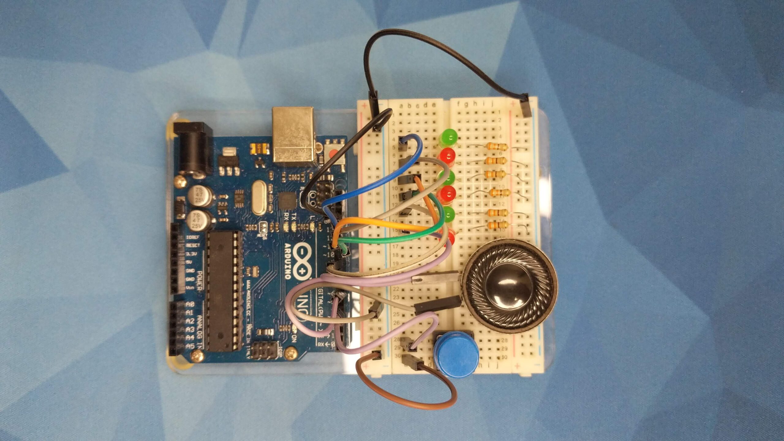
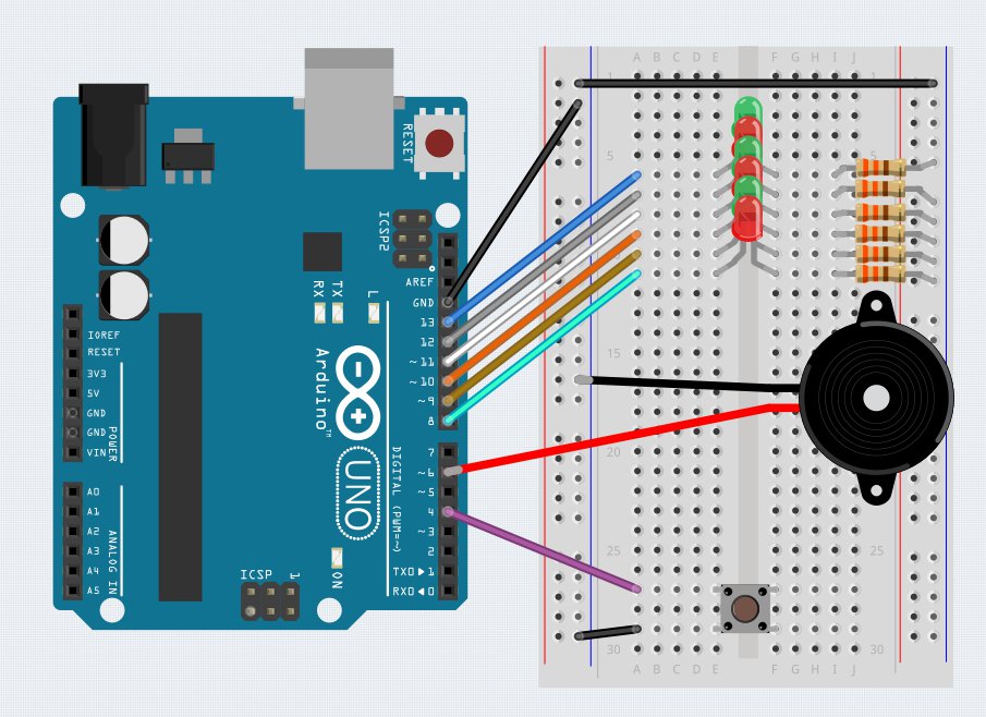
Christmas Ornament
This project features a Pushbutton, Speaker and 6 LED’s. LED’s have 330 ohm resistors connected in series to limit the current, but you could get away with anything up to 1kOhm without any issues. When the push button is pressed, the buzzer will play through a sequence of notes.
/*
Christmas Ornament Project - Damien Kee, 2019

Waits for a button press, and then plays Jingle Bells and flashes LED's

Hardware:
LED and Resistors (330 ohm to 1k should be fine) on Pins 8-13
Buzzer connected to 6 and GND
Button connected to 4 and GND

Music code original by Tom Igoe (2010) - http://www.arduino.cc/en/Tutorial/Tone

*/

// This list defines the note name and the frequency required to play it.  ie.  A concert pitch A in
// the 4th octave (A4) is 440Hz
#define C4  262
#define CS4 277
#define D4  294
#define DS4 311
#define E4  330
#define F4  349
#define FS4 370
#define G4  392
#define GS4 415
#define A4  440
#define AS4 466
#define B4  494
#define C5  523

int buzzer_pin = 6;   //Buzzer is connected to pin 6 and GND
int button_pin = 4;   //Button is connected to 4 and GND
int which_LED_is_on = 8;   // Variable to keep track of which LED is currently turned on

//Jingle bells melody.  An array is created, and each note defined within the array
int melody[] = {E4, E4, E4, E4, E4, E4, E4, G4, C4, D4, E4, F4, F4, F4, F4, F4, E4, E4, E4, E4, D4, D4, E4, D4, G4};

//Jingle Bell rhythm.  An array is created, where each entry in the array defines the length of the note in the melody array
// 1 = semibreve, 2=minum, 4=crotchet, 8=quaver
int rhythm[] = {4, 4, 2, 4, 4, 2, 4, 4, 4, 4, 1, 4, 4, 4, 4, 4, 4, 4, 4, 4, 4, 4, 4, 2, 2};

// Keep track of how many notes are in your melody
int number_of_notes = 25;


void setup() {
  // put your setup code here, to run once:
  pinMode(button_pin, INPUT_PULLUP);
  pinMode(13, OUTPUT);
  pinMode(12, OUTPUT);
  pinMode(11, OUTPUT);
  pinMode(10, OUTPUT);
  pinMode(9, OUTPUT);
  pinMode(8, OUTPUT);

}

void loop() {
  // put your main code here, to run repeatedly:

  // If the button is pressed, then run routine.  When the button is pressed, it connects the pin to GND, hence looking for the LOW signal
  if (digitalRead(button_pin) == LOW ) {
    // Create a 'for' loop.  Each time through the loop a melody note and the corresponding rhythm in each array are used with the tone() command
    // It will play through all the notes in the melody array using sizeof(melody).  Arrays are referenced from 0, so we need to subtract 1
    // Make sure rhythm array is the same length as melody array
    for (int thisNote = 0 ; thisNote< number_of_notes ; thisNote++) {

      //Turn on next LED
      digitalWrite(which_LED_is_on, HIGH);

      //The length of the note in miliseconds.  ie.  A quaver(8)  is 1000/8 = 125ms
      int noteDuration = 1000 / rhythm[thisNote];

      //make sure there is a very slight gap between each note by slightly shortening the notes.  10 milliseconds works well
      tone(buzzer_pin, melody[thisNote], noteDuration-10);

      //GIve the buzzer enough time to play the note (plus slight gap)
      delay(noteDuration) ;

      // Turn of LED
      digitalWrite(which_LED_is_on, LOW);

      // Increment the counter to point to the next LED
      if (which_LED_is_on == 13) {
        which_LED_is_on = 8;
      } else {
        which_LED_is_on++;
      }

    }
    noTone(buzzer_pin);
  }

}
Extension Ideas
- Program other tunes
- Have a random LED light up for each note
- Make a nicer case to present the project
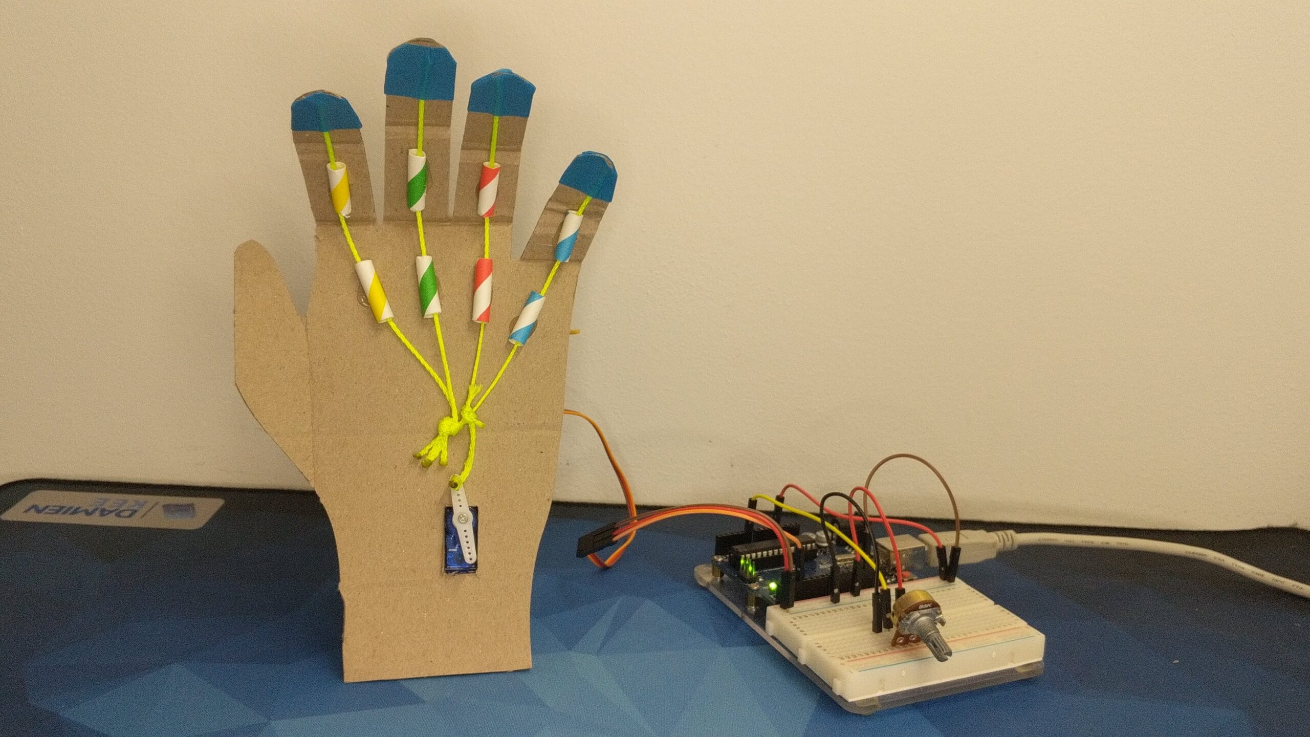
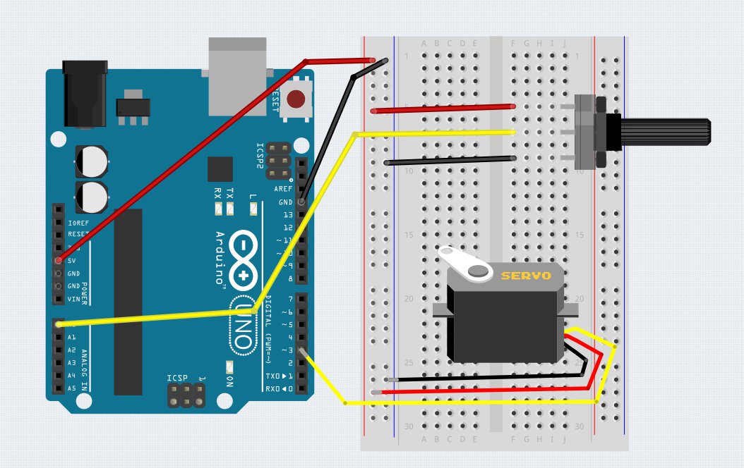
Hand
This project features a rotary Potentiometer and a Servo motor. As the potentiometer is turned, it creates a variable voltage that is then read by an Analog pins on the Arduino. When the AnalogRead function is called, it will give a range of 0 – 1023 depending on how far it has been turned. The Servo motor requires a control value of between 0 – 180. We use the map() function to do the maths required to make the change.
Strings running through straw tubes ‘pull’ the fingers shut. Rubber bands behind the fingers pull them back into position.
/*
 * Basic Gripper - Damien Kee 2020
 * Servo motor connected to Pin 3
 * Potentiometer connected to A0
 *
 * The Arduino reads in the potentiometer value (input).  This input will be between 0 and 1024
 * The "map" function then takes this input and scales it to be between 0 and 110.
 * The 0 and 110 are figured out experimentally by seeing what angles the servo motor needs to rotate to
 */

#include <Servo.h>

Servo hand;
int input = 0;
int output = 0;

void setup() {
  hand.attach(3);
  Serial.begin(9600);
}

void loop() {
  input = analogRead(A0);                 // Read in the Potentiometer value
  output = map(input, 0, 1024, 0, 180);   // Convert the input to a number the servo can use
  hand.write(output);                     // Make the servo move to that location
  Serial.println(output);                 // Send the servo angle back to the computer (Serial Monitor) for debugging
  delay(100);                             // Slight delay to allow the servo to catch up

}
Extension Ideas
- Make each finger controlled by a separate Servo motor
- Use multiple pushbuttons to put the hand into preset configurations
- Use a ‘flex’ sensor embedded in a glove to control the Servo motor
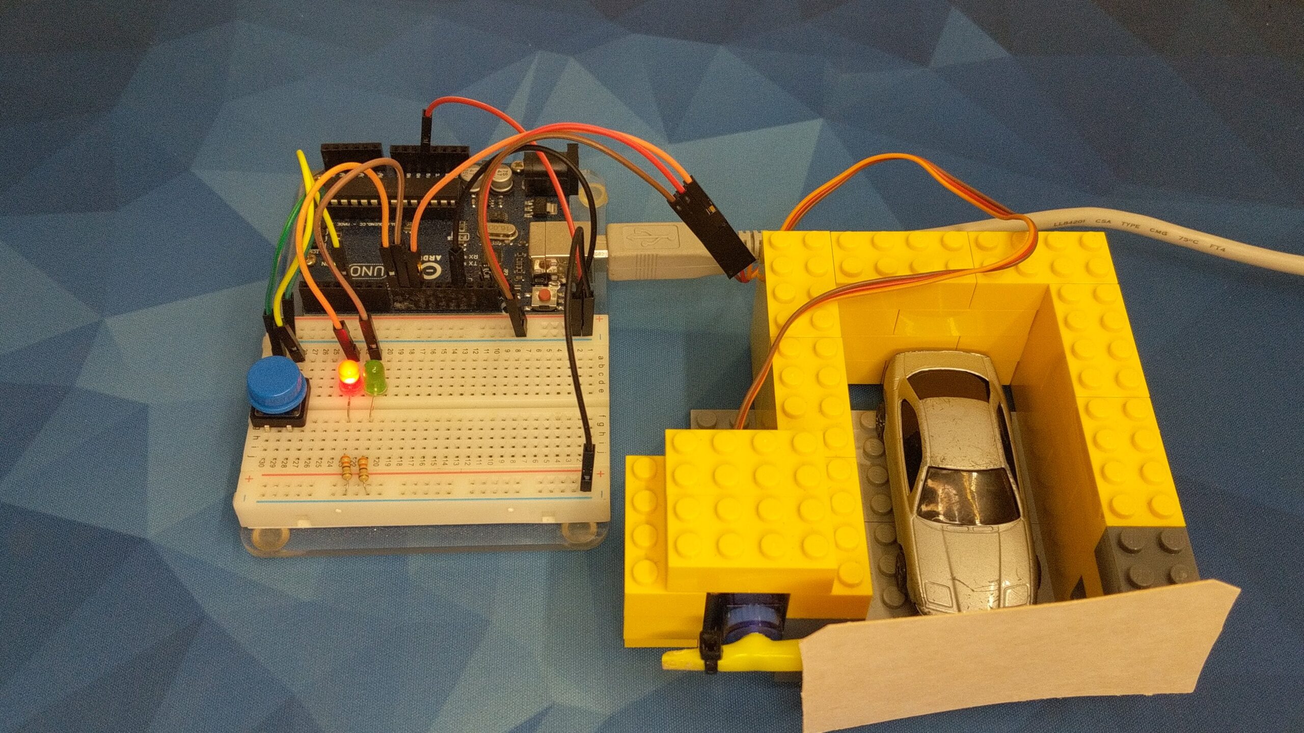
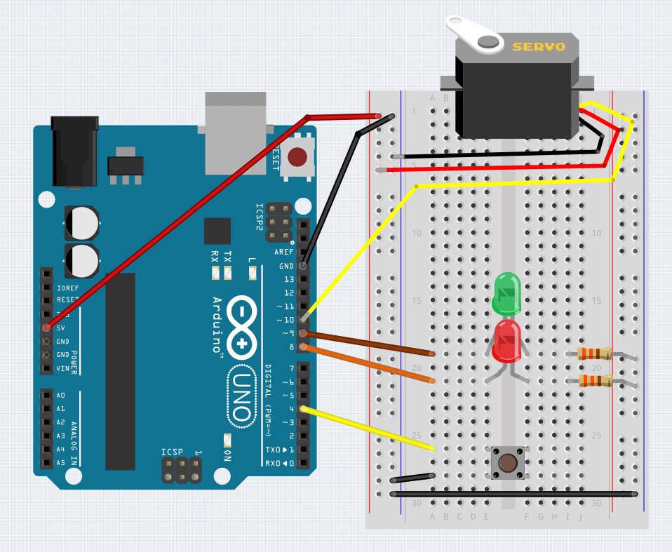
Garage Door
This project features a Pushbutton, 2 LED’s and a Servo motor. The Red LED starts on. When the button is pressed, the servo motor rotates to lift the garage door, and the LED’s switch from Red to Green. After a short pause, the door closes and the LED’s switch back.
/*
 * Garage Door Opener - Damien Kee 2019
 * Sevo motor connected to pin 10
 * Red and Green LED's on 8 and 9 (330ohm resistors to GND)
 * Button on Pin 3
 */

//Include the Servo Library that does all the nitty-gritty servo code
#include <Servo.h>

//LEDs are connected to pins 8 and 9, button is on 4
int GREEN = 9;
int RED = 8;
int button_pin = 4;

Servo door;   //Define the Servo object

void setup() {
  // put your setup code here, to run once:
  door.attach(10);      // Tell the Arduino there is a Servo attached to pin 10
  pinMode(GREEN, OUTPUT);
  pinMode(RED, OUTPUT);
  pinMode(button_pin, INPUT_PULLUP);
}

void loop() {
  door.write(5);            // Tell the servo to go to the 0 degree position
  digitalWrite(RED, HIGH);  // Red light on, green light off
  digitalWrite(GREEN, LOW);

  //If the button gets pressed
  if (digitalRead(button_pin) == LOW) {
    digitalWrite(RED, LOW);
    digitalWrite(GREEN, HIGH);
    door.write(90);
    delay(2000);
  }
}
Extension Ideas
- Use a distance sensor (Infrared or Ultrasonic) to detect when a car is approaching
- Add a buzzer to indicate when the door is opening or closing
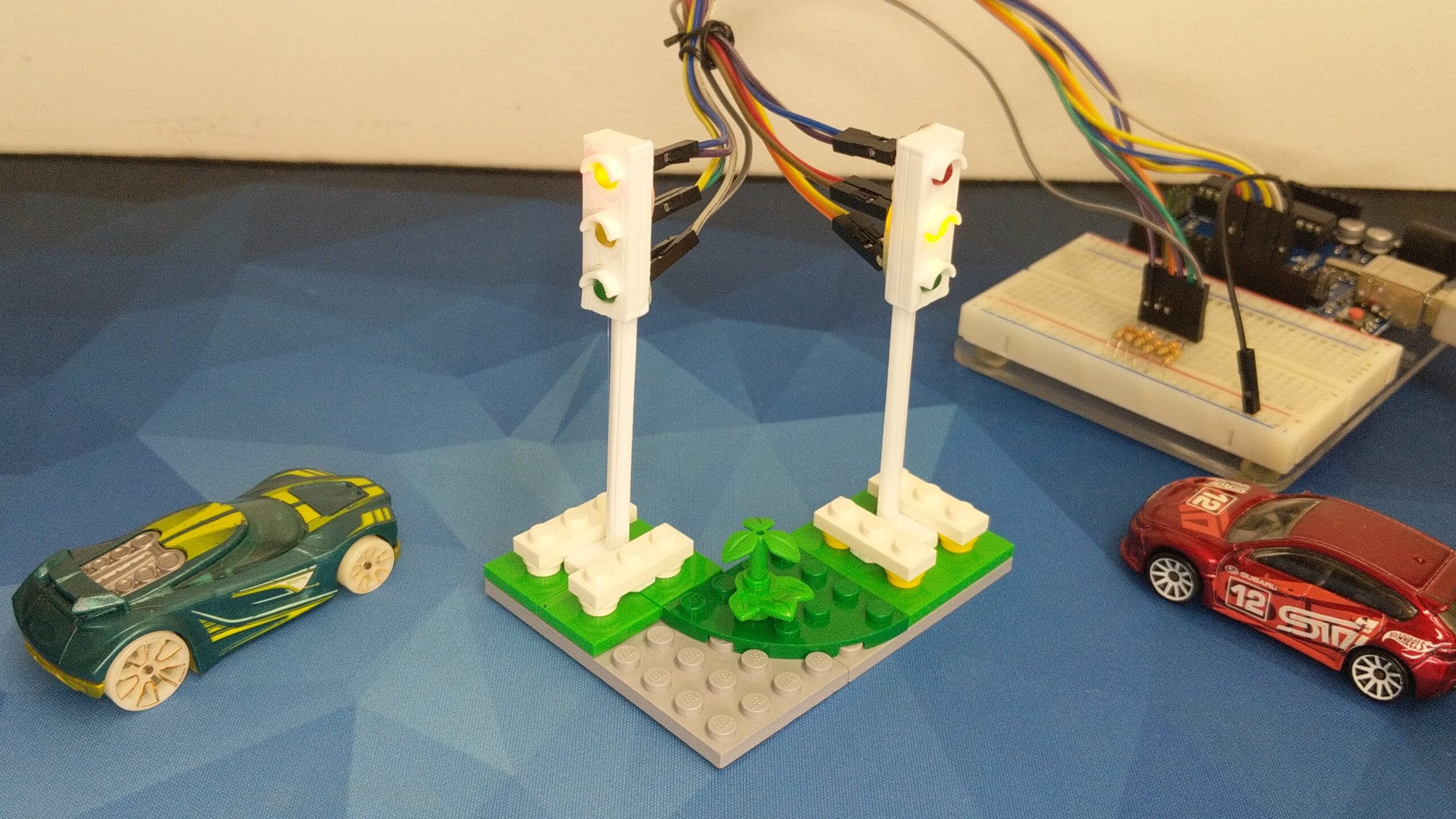
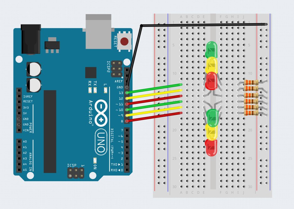
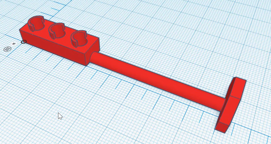
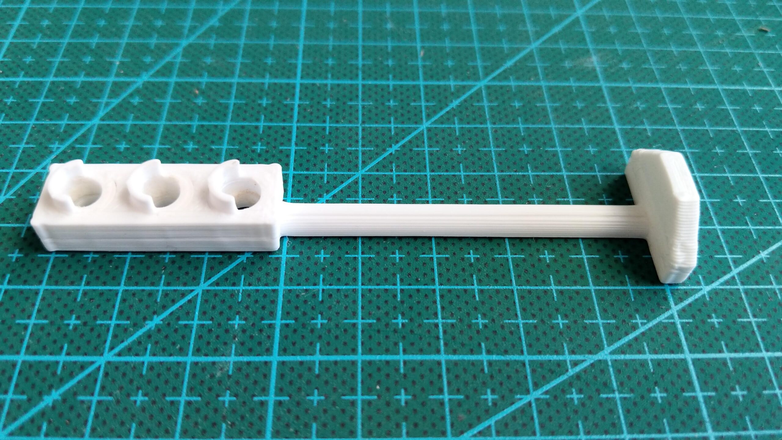
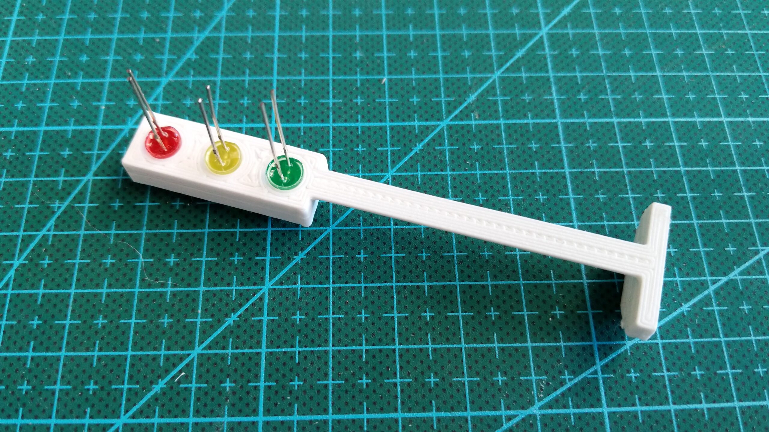
Traffic Lights
This project features 6 LED’s. The LED’s are arranged in two sets of Green/Orange/Red just like real life traffic lights. The Arduino code cycles through a sequence of Green – Orange – Red and back to Green, in such a way to ensure that only one set of lights is Green at any time. I designed some simple traffic lights in TinkerCad ensuring it could be printed without any supports. A bit of hot glue holds the LED’s in place.
/*
 * Two way Traffic Lights - Damien Kee 2020
 * 2 sets of traffic lights (Green, Yellow, Red). One facing North, the other facing west
 * Traffic lights change through a sequence to ensure no crashes
 * LED's have a 330 ohm resistor in series to limit the current.
 */

int north_red = 8;
int north_yellow = 9;
int north_green = 10;
int west_red = 11;
int west_yellow = 12;
int west_green = 13;

void setup() {
  pinMode(north_red, OUTPUT);
  pinMode(north_yellow, OUTPUT);
  pinMode(north_green, OUTPUT);
  pinMode(west_red, OUTPUT);
  pinMode(west_yellow, OUTPUT);
  pinMode(west_green, OUTPUT);

}

// Not the most efficient code, but does highlight the state of every LED for each part of the sequence
void loop() {
  digitalWrite(north_red, HIGH);
  digitalWrite(north_yellow, LOW);
  digitalWrite(north_green, LOW);
  digitalWrite(west_red, LOW);
  digitalWrite(west_yellow, LOW);
  digitalWrite(west_green, HIGH);
  delay(3000);

  digitalWrite(north_red, HIGH);
  digitalWrite(north_yellow, LOW);
  digitalWrite(north_green, LOW);
  digitalWrite(west_red, LOW);
  digitalWrite(west_yellow, HIGH);
  digitalWrite(west_green, LOW);
  delay(1000);

  digitalWrite(north_red, HIGH);
  digitalWrite(north_yellow, LOW);
  digitalWrite(north_green, LOW);
  digitalWrite(west_red, HIGH);
  digitalWrite(west_yellow, LOW);
  digitalWrite(west_green, LOW);
  delay(1000);

  digitalWrite(north_red, LOW);
  digitalWrite(north_yellow, LOW);
  digitalWrite(north_green, HIGH);
  digitalWrite(west_red, HIGH);
  digitalWrite(west_yellow, LOW);
  digitalWrite(west_green, LOW);
  delay(3000);

  digitalWrite(north_red, LOW);
  digitalWrite(north_yellow, HIGH);
  digitalWrite(north_green, LOW);
  digitalWrite(west_red, HIGH);
  digitalWrite(west_yellow, LOW);
  digitalWrite(west_green, LOW);
  delay(1000);

  digitalWrite(north_red, HIGH);
  digitalWrite(north_yellow, LOW);
  digitalWrite(north_green, LOW);
  digitalWrite(west_red, HIGH);
  digitalWrite(west_yellow, LOW);
  digitalWrite(west_green, LOW);
  delay(1000);


}
Extension Ideas
- Create a 4-way intersection
- Add Pedestrian crossing lights triggered by a pushbutton
- Use a distance sensor (Infrared or Ultrasonic) to detect when a vehicle has pulled up to the lights.
This is a timelapse of the process of designing the Traffic Lights in TinkerCad.